Virtual Exhibition 2020
From Saturday 28th November several of our members will be exhibiting some of their creations here on the website. This is in place of our annual exhibition that we would normally hold at this time of year.
Click on each Title for more information and photos
 8 Day Wall Clock
 5″ Gauge Crampton Loco
 7 1/4″ Gauge Quarry Hunslet
 Gravity Escapement Regulator Clock
 Filing Rest
 Knurling Tool
 O Gauge 20ton LowMac Wagon
 O Gauge 21ton Trestle Wagon
 O Gauge 45ton Bolster Wagon
 O Gauge Old Gentleman’s Saloon
 7 1/4″ Gauge DBS Litra HS
 Middleton Twin Cylinder Engine
 Beam Engine
 2″ Scale Foden Wagon
 Clayton and Shuttleworth Steam Wagon
 John Wilding 3/4 Second Hipp Clocks
 Manx Electric Railway Tram Number 1
 3 1/2″ Gauge Rob Roy
 5″ Gauge Britannia Class Loco
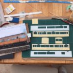
 Building a Signal Panel
Building a Signal Panel
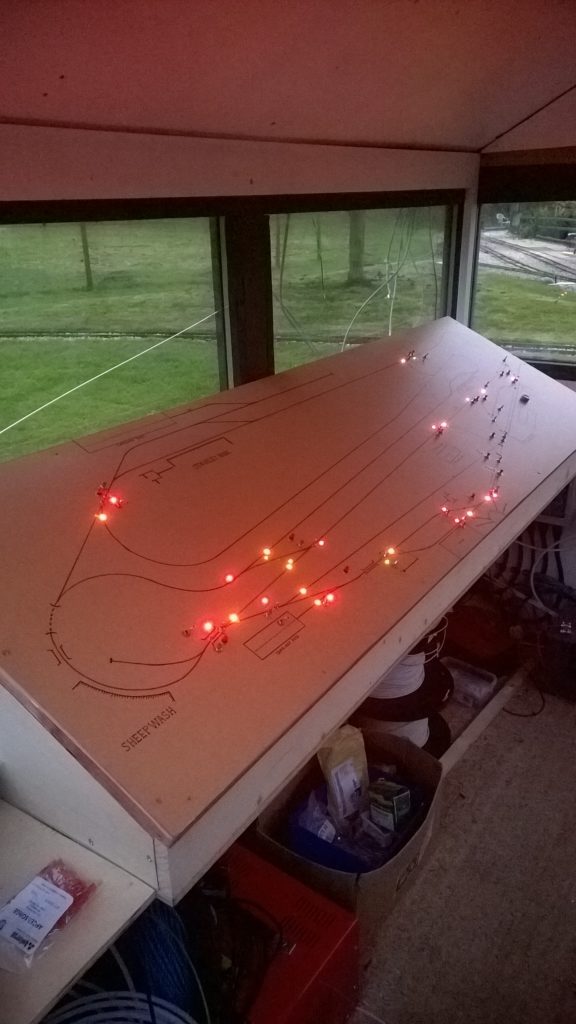
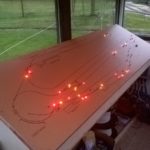
Building a New Signal Panel for a Miniature Railway
Initially a lot of planning and design work was done around the site and once the specification was finished work could start on the circuit design, digging conduit trenches and pulling in miles of cables and air lines. Initially this panel was supposed to be a temporary one while a digital design was completed but it has now been in use for 5 years and is likely to stay!
The track was split up into ten main sections each with it’s own electrical circuit, the most complex was the station area show above. All the points are air operated with most of the signals LED and a few semaphore. All the points are interlocked with the signals to prevent accidental changes but there is always the human factor. Development work is currently ongoing with additional interlocks and train detection on the track.
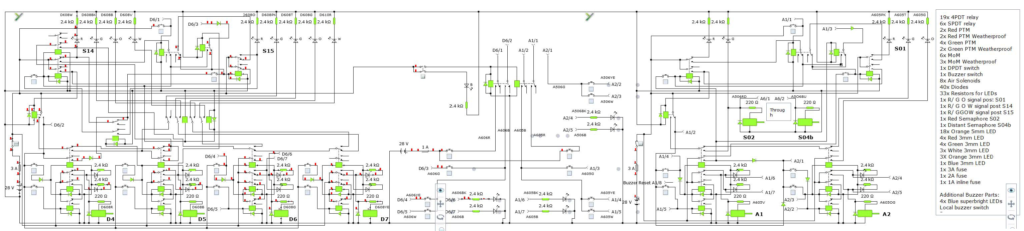
It was anticipated that changes would be made to the track layout in the future so to allow easy modifications and keep the costs minimal basic relays were used.
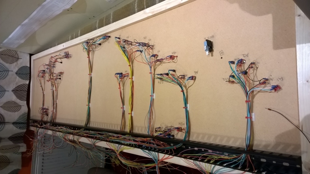
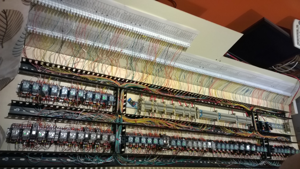
There are around 240 connections from the base of the panel up to the top control surface and 102 connections going in and out of the panel to the signals/points and remote controls. There are 22 signals currently on the system, 17 points and a level crossing gate on air control.
5″ Gauge Britannia Class Loco
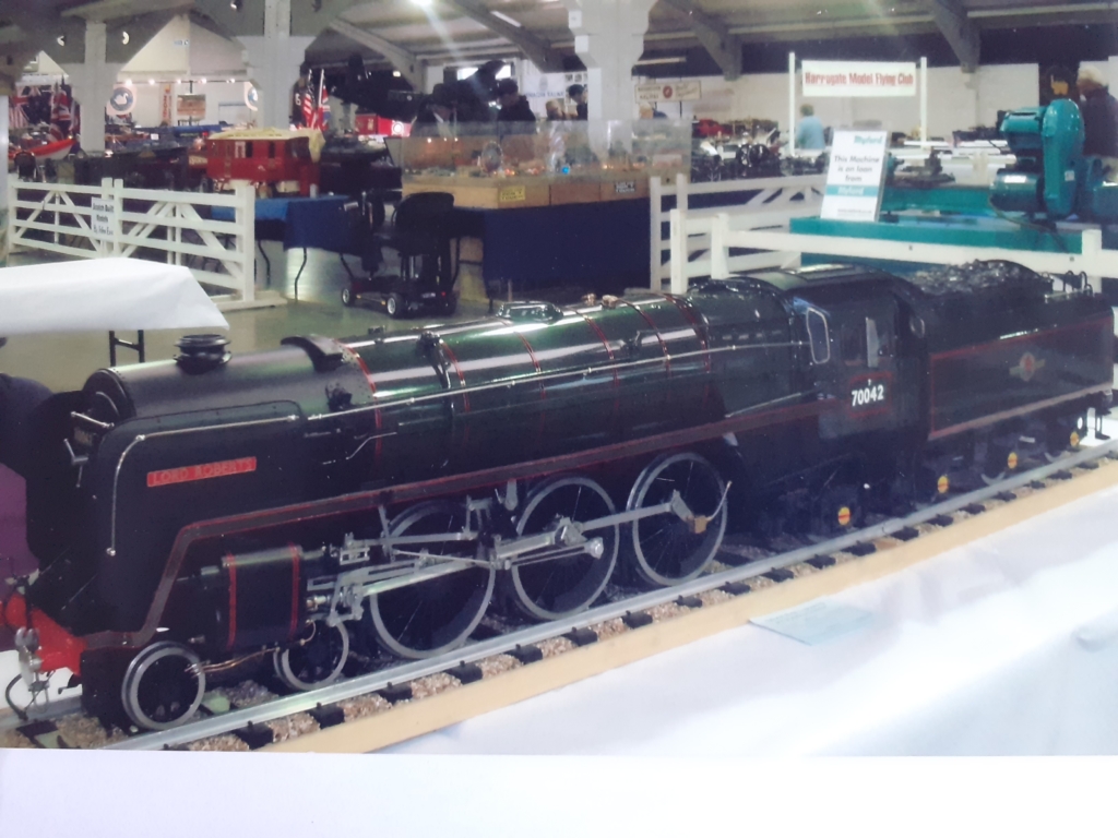
5″ Gauge Britannia Class Loco 70042 “Lord Roberts”
(currently having a new design of regulator fitted)
3 1/2″ Gauge Rob Roy
3 1/2″ Gauge Rob Roy
(recently refurbished)
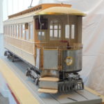
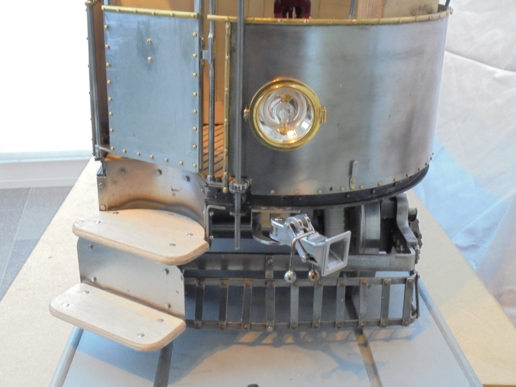
Manx Electric Railway Tram Number 1
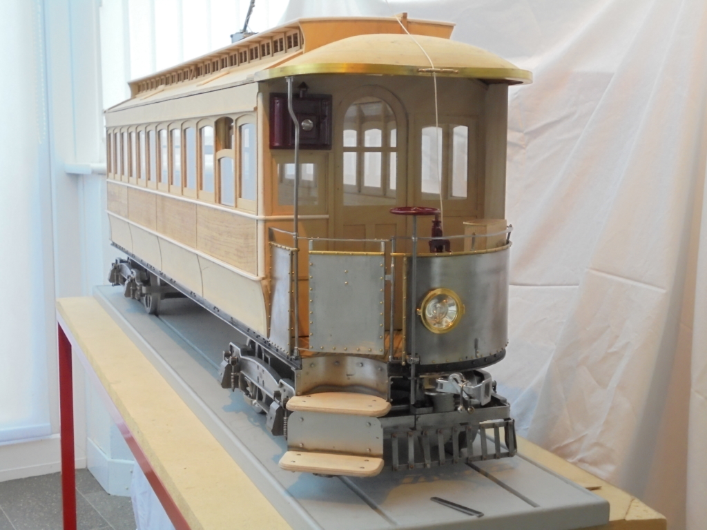
Isle of Man Manx Electric Railway Tram Number 1
This is a 5″ gauge (the width of the rails) model of MER 1 from 1893.
The full size tram is in the Guinness Book of Records as the oldest tram still running on its original track in the Isle of Man.
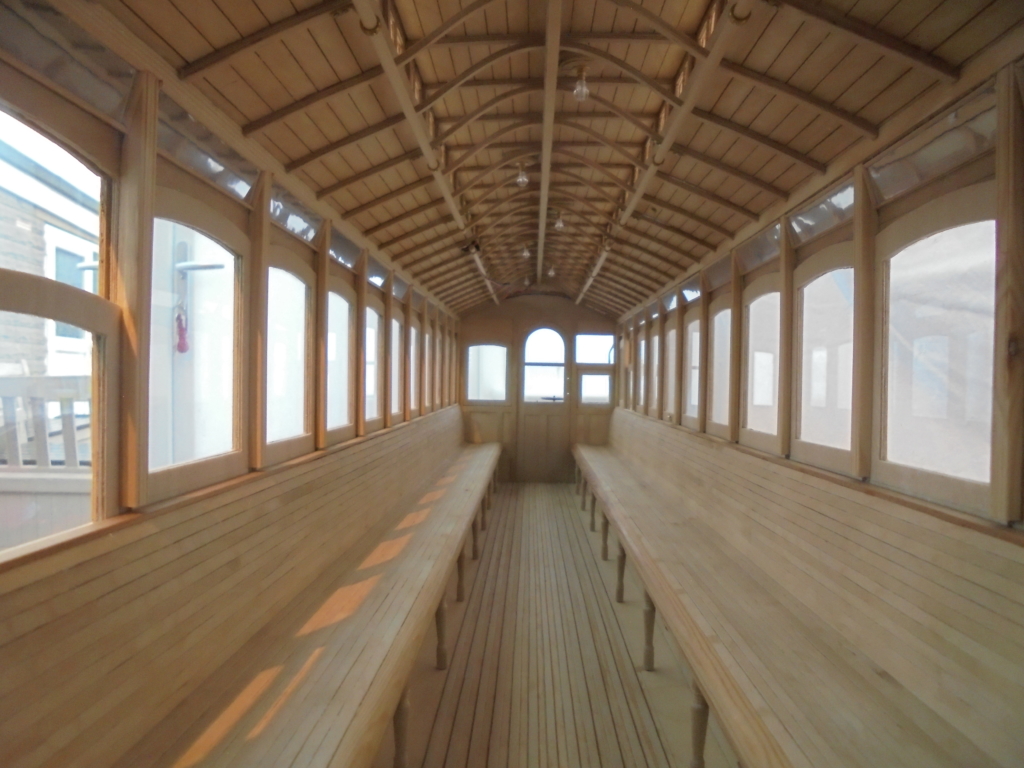 The model is scratch built, meaning that every thing has had to be made, except for a few things like electric motors, bearings and some nuts and bolts.
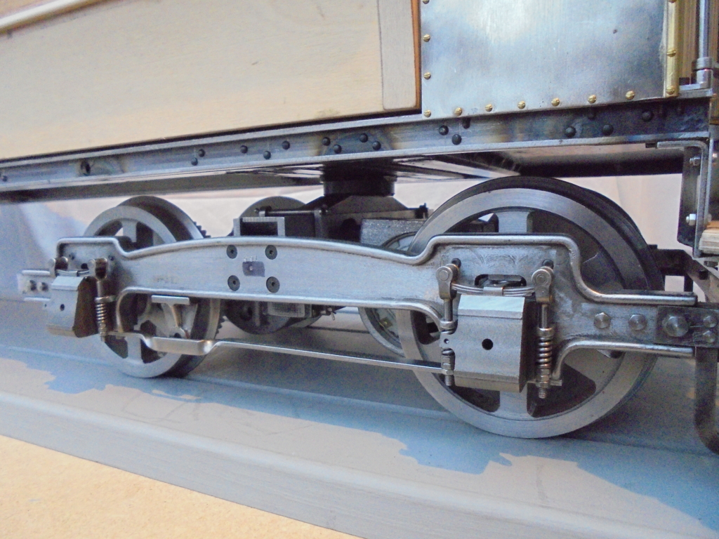 There are no detailed dimensioned drawings available so all I could find was a side view line drawing in a book along with one for the bogies, these were enlarged to the size of the model which gave a good idea of the proportions. It was then down to researching books and photographs.
As the full size tram is still running, holidays on the Isle of Man were a must and the staff at the depot in Douglas were so helpful and enthusiastic about my project. A considerable number of photos and measurements were taken.
 The tram will be powered by two 12 volt batteries, so, when running, parts of the interior will be removed and the batteries and electronics dropped in.
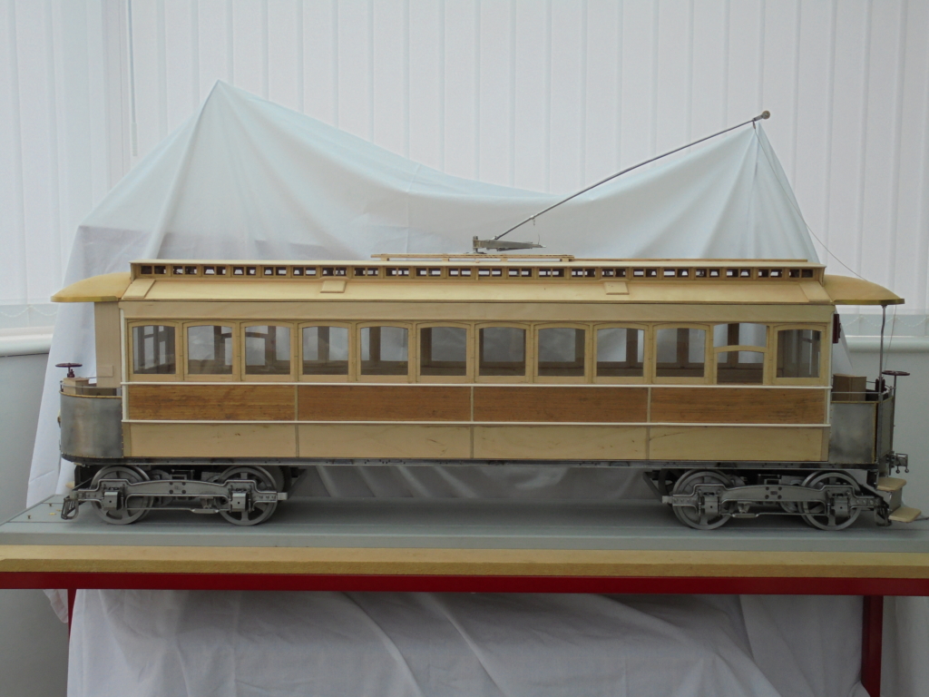 This has taken 4 years so far with the detailing taking the most time. The next challenge will be painting!
John Wilding 3/4 Second Hipp Clocks
John Wilding 3/4 Second Hipp Clocks
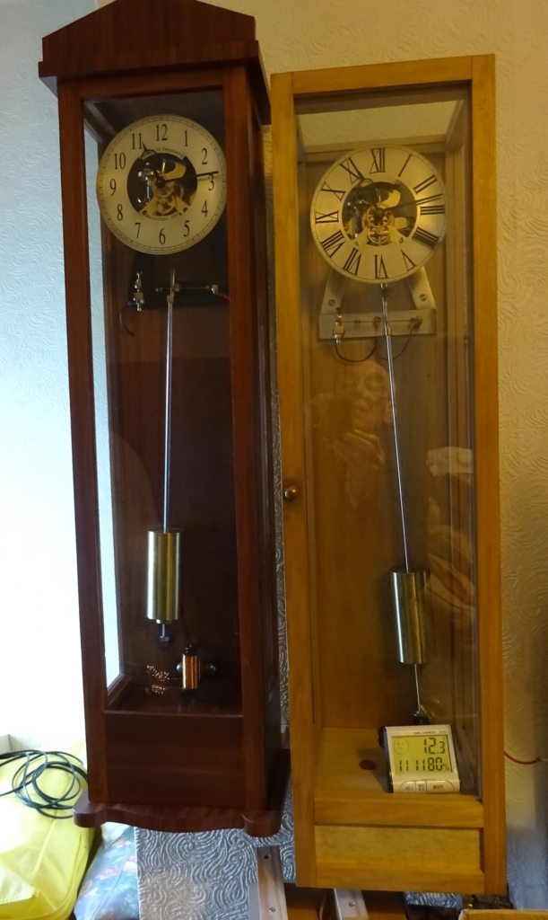
These clocks are modelled on a John Wilding design. With most clocks, the power is supplied by either weights or a spring; with the Hipp-toggle clock the pendulum provides the power, as well as regulating the clock.
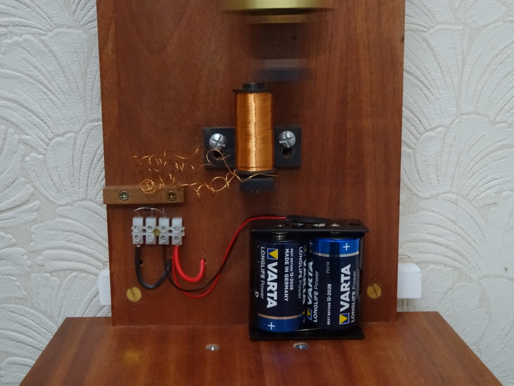
The power comes from a couple of 1.5V batteries, delivered via an electromagnet.
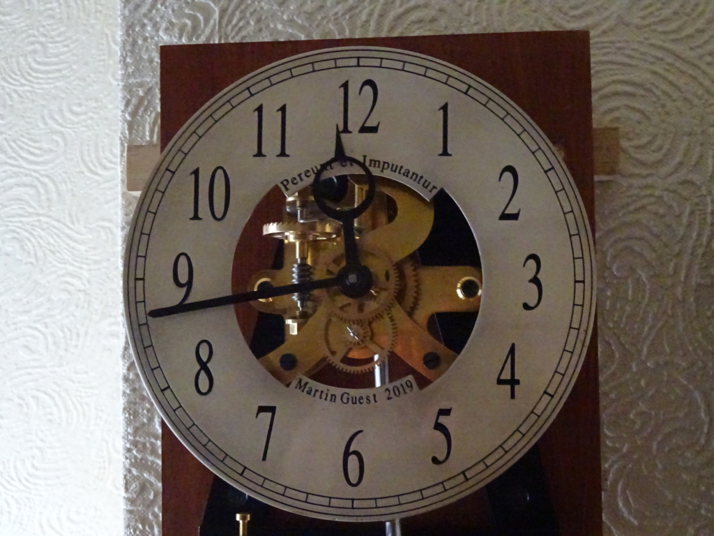
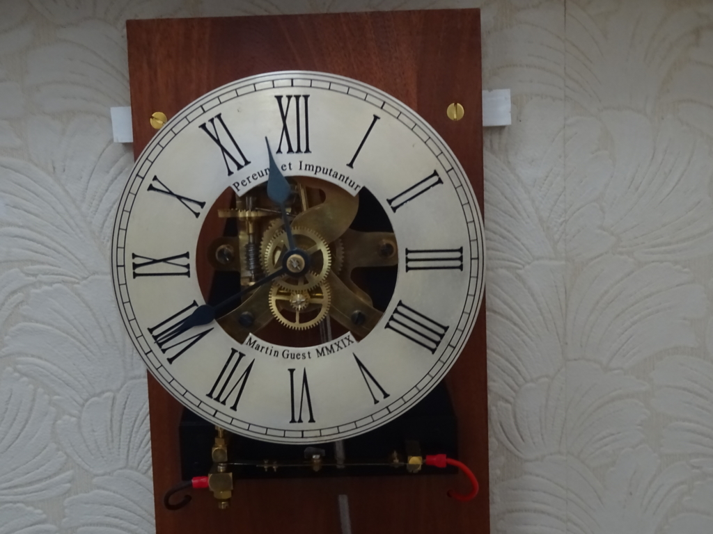
One deviation from the John Wilding design is the clock dials. I couldn’t decide if I preferred Roman or Arabic numerals, so drew up both on Autocad. They were then photo-etched and delivered to me as etched brass sheets. These were cut and filed to size, sprayed black for the numerals, polished back to brass, silvered and then lacquered.
The cases are to my own design. They comprise a backboard and base, wall mounted, and a hood. The hood can be removed for access.
These clocks can be noisy, so the backboards are19mm veneered MDF. The hoods are composite – 12mm veneered MDF for quietness, with a ply outer for strength. Veneer covers the ply.
 The cases have modest ornamentation – I didn’t want them to be wholly plain, but I didn’t want them to be too fussy either. The result is a crest-board on top, with a pedestal underneath. The bottom board is profiled so sharp edges are avoided.
I started out to make one clock, however my workmanship is so bad that I ended up making at least one additional of each component, so it seemed a waste not to make them into a second clock.
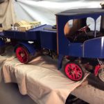
Clayton and Shuttleworth Steam Wagon
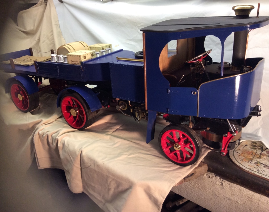
2” Scale Clayton and Shuttleworth Articulated Steam Wagon
Under type single cylinder
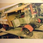
2″ Scale Foden Wagon
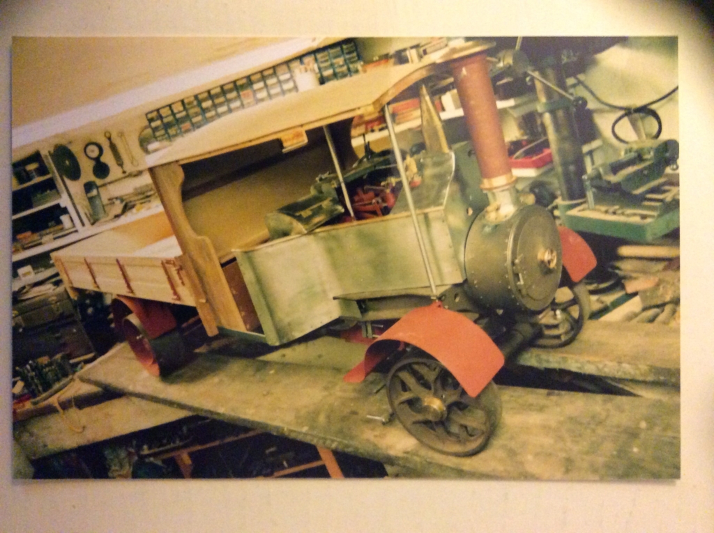
Unfinished 2” Scale Compound Foden Steam Wagon
(still on the bench!)
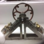
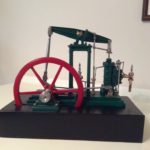
Beam Engine
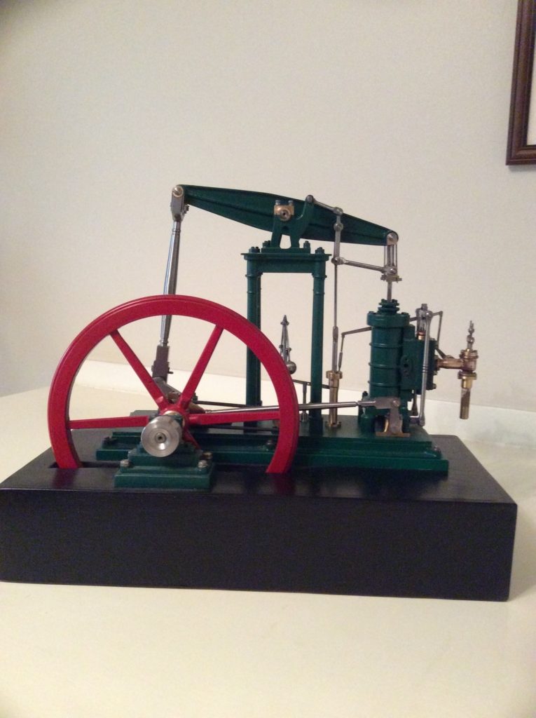
Four Column Beam Engine to the Tubal Cain Design
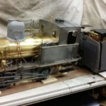
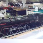
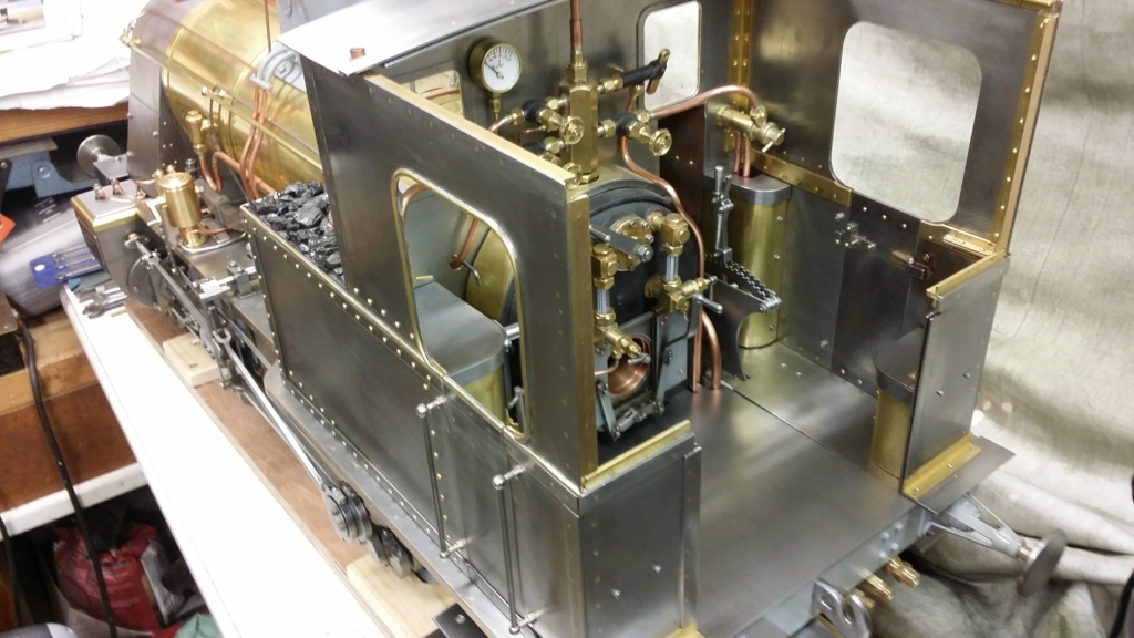
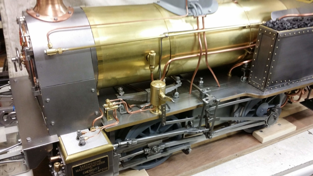
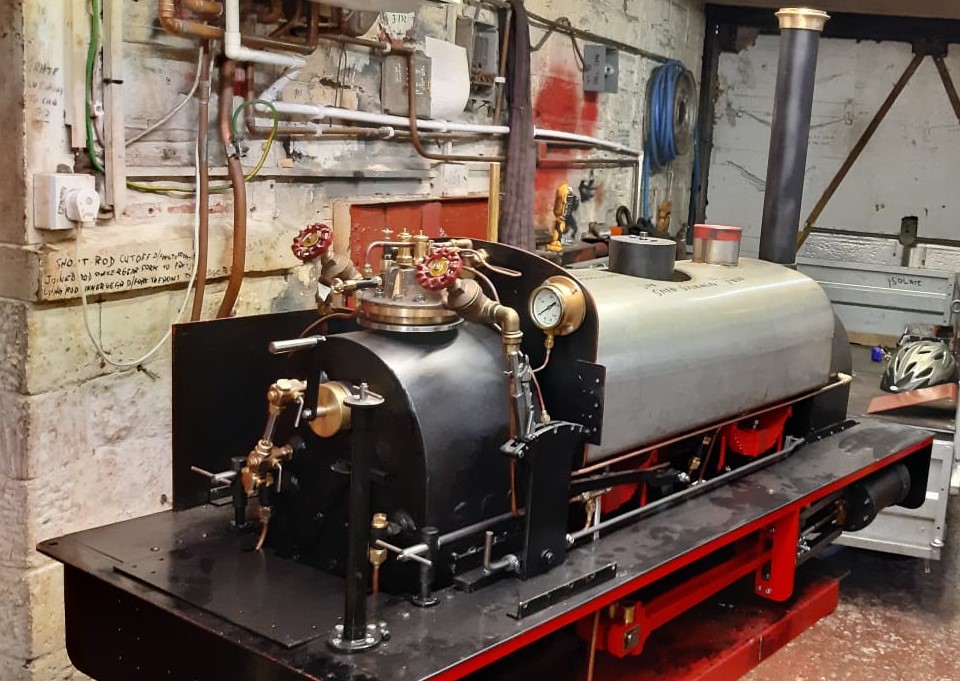
7 1/4″ Gauge DSB Litra HS
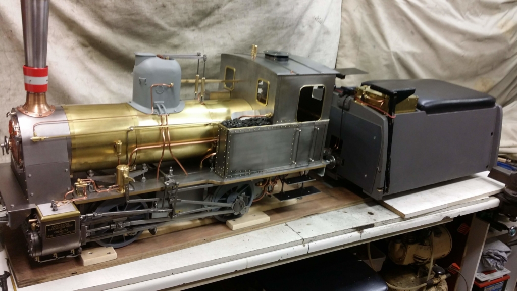
7 1/4″ Gauge DSB Litra HS
The locomotive is a 7¼” gauge model of a 0-4-0WT (WT denotes well tank) locomotive based on locomotive No. HS 385 now residing at the Middleton Railway Museum in Leeds.
The model is being built from scratch based on two drawings obtained from the Danish Railway Museum. The drawings were originally drawn in 1874 and revised in 1901. These drawings, which are drawn to 1/10 metric scale, show a plan, elevation and three sections. These have been reproduced to true 7¼” scale.
Construction of the model started February 2013. As no castings are available so the wheels have been machined from mild steel and the cylinders from cast iron blocks. The copper boiler has been fitted with a superheater and has been tested and certified to operate at 90 psi. The original boiler water feed was by two steam injectors but the model has been fitted with a water pump from the well tank, driven by an eccentric fitted to the front axle, to continually feed the boiler when in motion. There will also be a steam injector fitted.
Middleton Twin Cylinder Engine
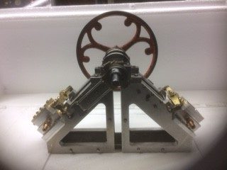
Middleton Twin Cylinder Engine, V Type
O Gauge Old Gentleman’s Saloon
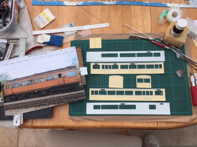
O Gauge Old Gentleman’s Saloon
This is the start of an O gauge model of “ The Old Gentleman’s saloon” from the Railway Children film. Earlier this year a model company called Dapol issued a model of a Great Western pannier tank in the fictitious Great Northern & Southern Railway livery used in the film. Being one of the assistant station masters at Oakworth station I thought it might be a good idea to recreate the Old Gentleman’s train with the loco and 3 coaches used, to display at the forthcoming 50th anniversary event in May 2021 hopefully. The actual anniversary is 2020 but for obvious reasons it’s had to be postponed.
I obtained a kit to build the Metropolitan Railway 9 compartment 3rd and the NER 1st class 6 wheeler.
As no one does a kit for this coach it’s being constructed from from scratch in Plasticard with a brass chassis. This is a new method of working for me and involves a lot of research including measuring and photographing the full size vehicles, fortunately they are available at Oxenhope or The Vintage Carriage Museum at Ingrow by arrangement.
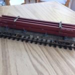
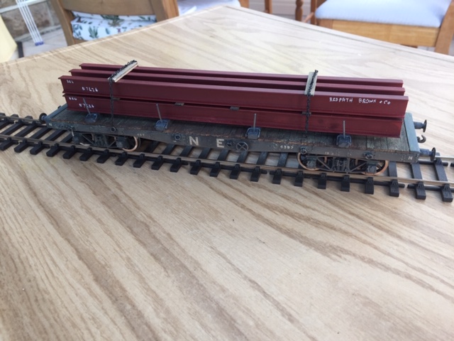
O Gauge 45ton Bolster Wagon
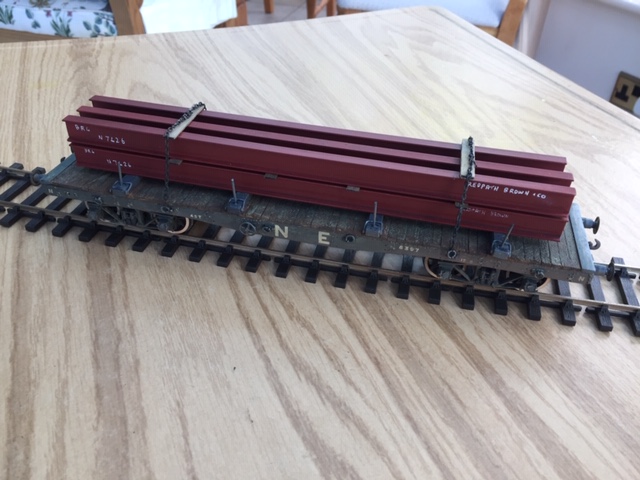
O Gauge 45ton Bolster Wagon
This is a model of an LNER/BR 45 ton bogie bolster wagon built from an ABS models cast white metal kit. It was acquired second hand and quite badly built so required restoration and repainting.
The load of RSJ’s are made from lengths of pre formed plastic moulding painted in red oxide primer.
Rebuilt, painted and lettered by the owner.
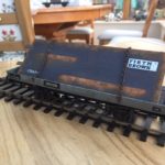
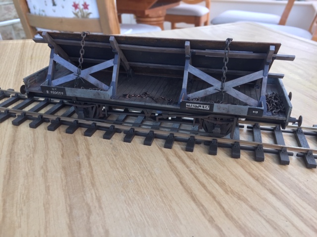
O Gauge 21ton Trestle Wagon
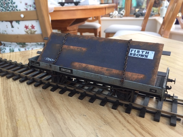
O Gauge 21ton Trestle Wagon
This is an O gauge model of a 21 ton BR trestle wagon built from a Parkside Dundas plastic kit. They were converted from Plate wagons by the addition of the trestle to carry oversize loads of steel which were too wide to lie flat.
The load on this wagon started off as a sheet of aluminium which was painted and weathered to look like new rolled steel plate.
Built painted and weathered by the owner.
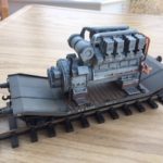
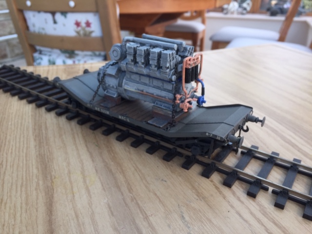
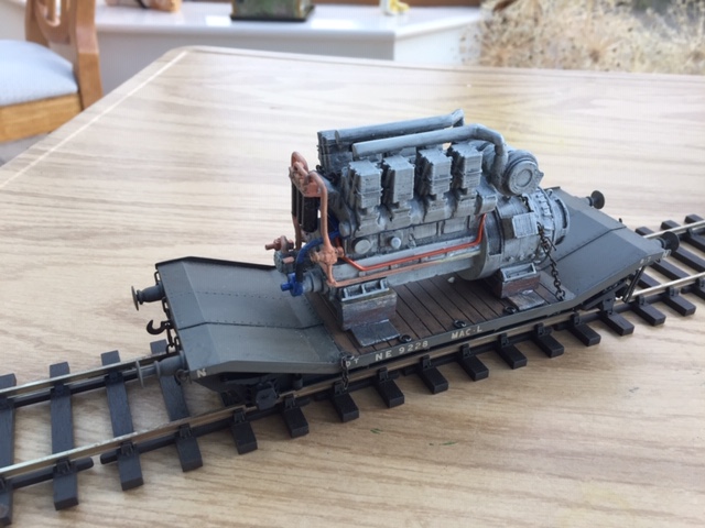
O Gauge 20ton LowMac Wagon

O Gauge 20ton LowMac Wagon
This is an O gauge model of an LNER/BR 20 ton LowMac wagon built from a Connoisseur models etched brass kit. The load is an English Electric 8SVT V8 turbo diesel from a Class 20 locomotive, built from an SBT models resin kit the castings of which were pretty poor and took a lot of cleaning up but it doesn’t look too bad now.
It was built, painted and weathered by the owner.
Knurling Tool
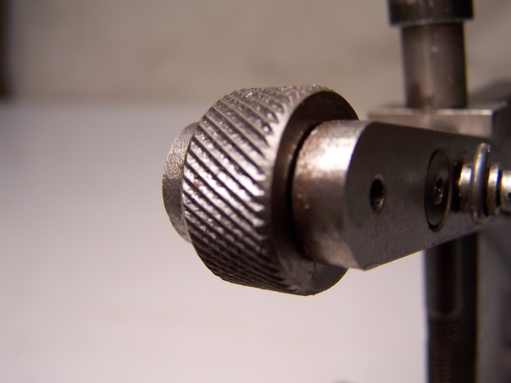
Knurling Tool
Where a knurled finish is required, the knurling tool is fitted to the lathe whilst the item to be knurled is still in the lathe chuck. The two knurling wheels impart the cross-hatched pattern on the item as the work is rotated on the lathe. Each hardened wheel has the same pattern and, as the two wheels are pressed into the work, a diamond pattern is produced.
This knurled finish can be easily gripped by hand and rotated without the hand slipping. Although commercial knurling tools are available, these are limited to knurling items less than 50mm (2 inches) in diameter. This one was specially made to knurl items up to 75mm (3 inches) in diameter for a specific job.

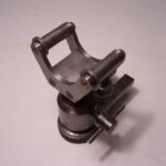
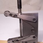
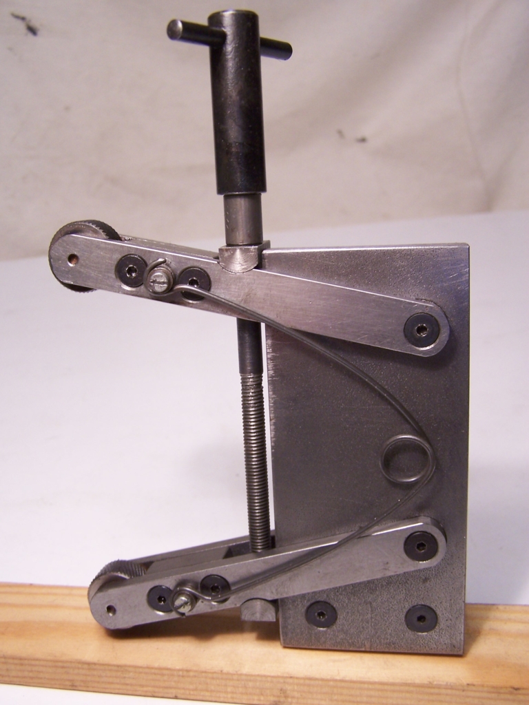
Filing Rest
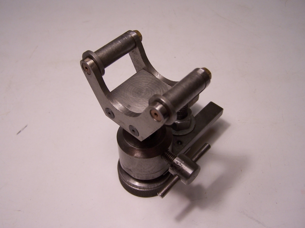
Filing Rest
Sometimes it is necessary to put flats onto a round bar, so that it can be turned with a spanner. This is where the filing rest comes in. These are not available commercially, so have to be tailor-made to fit the lathe on which it is used.
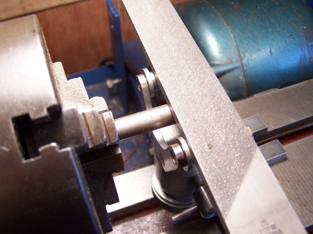 There are two rollers with small flanges used to guide the file. Once the part is ready to have the flats filed, the lathe spindle is locked and the file used to file the flat. The flanges stop the file drifting too far up the round bar, and the filing rest is adjusted in height so that the right amount of material is filed off to give the correct size of flat and the file no longer removes any material.
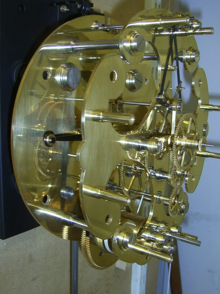
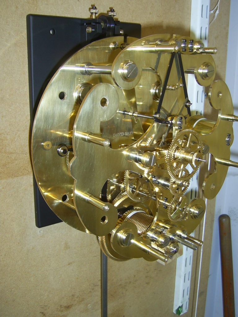
Gravity Escapement Regulator Clock
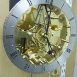
Gravity Escapement Regulator Clock
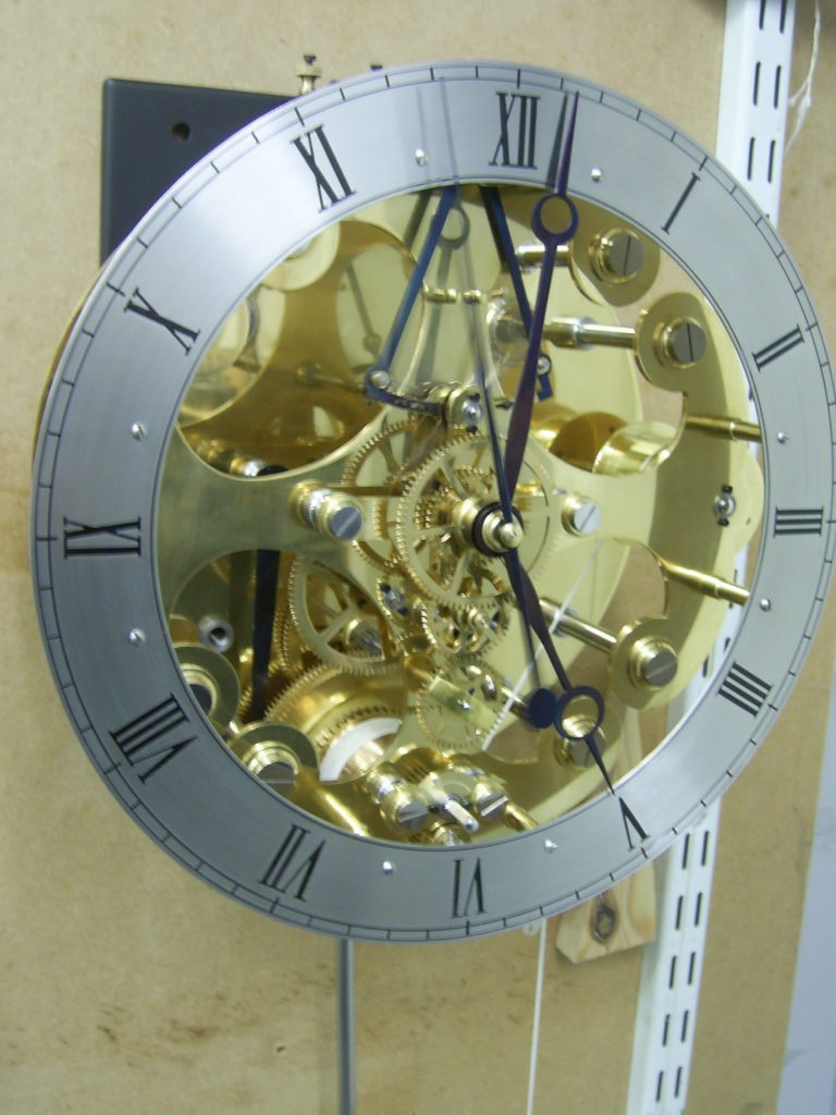
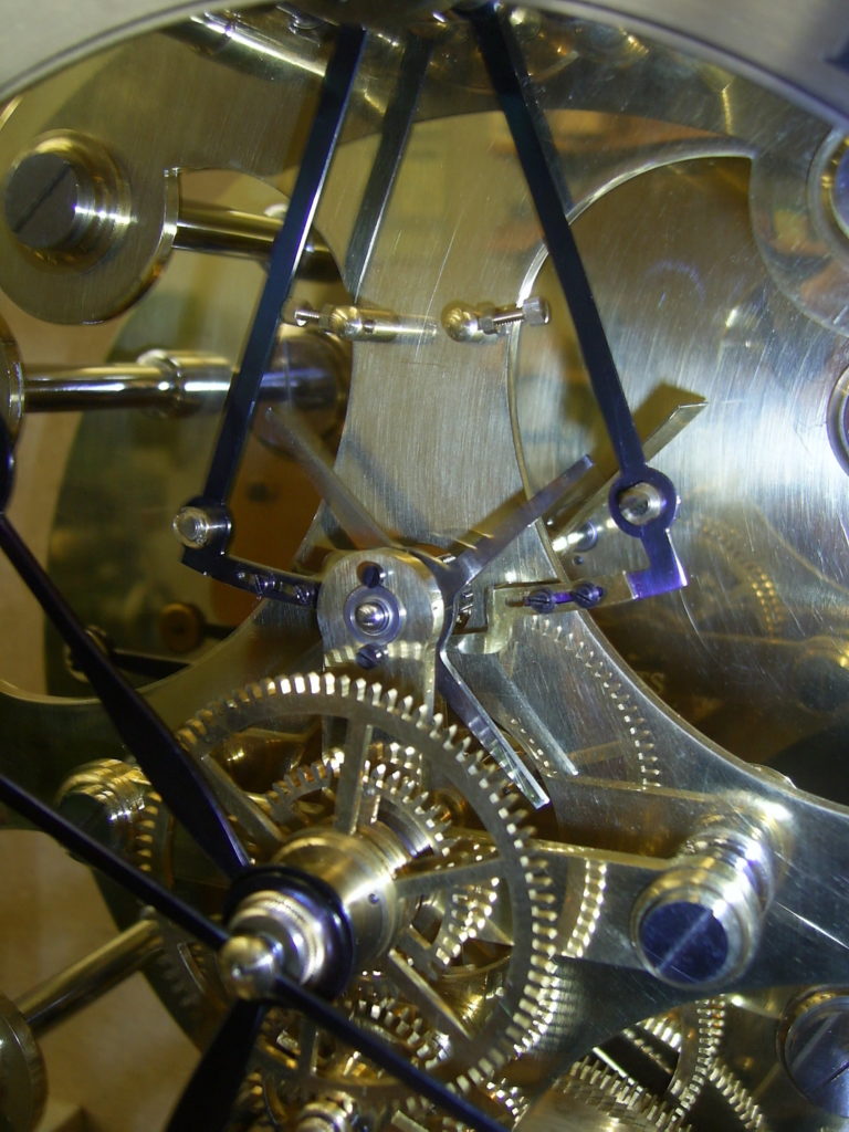
Another clock, this time a 4 leg Gravity Escapement Regulator Clock, based on the late Claude Reeve design originally published in the Model Engineer magazine in 1960.
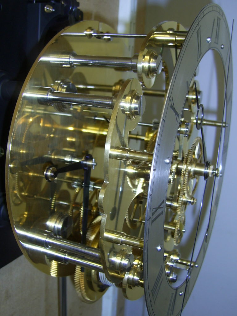 This clock is quite challenging to make in that the overall gear ratio between the driving force and the escapement is 5400:1 rather than the more usual 720:1 found in most clocks. This means that the power available to drive the escapement is only about one eighth that normally available which demands that the clock be very free running, accurately made and finely balanced if it is to work reliably.
As with most constructors, I have modified the original design to suit my own preferences. In particular I fitted precision ball races throughout, designed a more substantial English regulator style back plate and pendulum mounting, new pendulum temperature compensation and regulation arrangements, different maintaining works etc.
I also found it necessary to re-design the escapement. I made the first version “to the book” but found its operation to be unreliable, with the escape wheel failing to lock reliably and occasionally skipping past the locking pins. Articles from the authors of several subsequent versions indicated this seems to have been a common problem. I eventually located what I thought to be the problem in the original design layout. Once redesigned to correct the problem, I made a new set of escape arms which were fitted and, once properly adjusted, seem to work well.
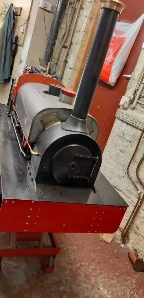
7 1/4″ Gauge Quarry Hunslet
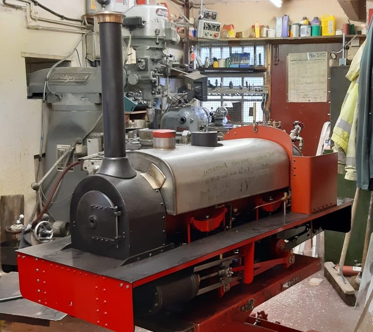
7 1/4″ Gauge Quarry Hunslet
 The very last train to San Fernando!!
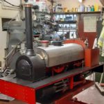
This 7 1/4″ gauge Hunslet is a 4″ scale model of LILLA built circa 1890 for the Cilgwyn Quarry but is now still in operating condition for the Ffestiniog Railway.
This model was started by BMES member about 25 years ago. The completed chassis and castings were purchased at a later date by another BMES member but no further work was done until I purchased it in 2005.
I commenced work on it about 2008, the boiler is steel, built in my own workshop and welded by a very skilled retired professional boiler welder, fortunately I have a 3 phase electric supply. It has a club hydraulic certificate to 110 psi and also a commercial test to same value.
All paintwork below footplate is completed.
The engine is now ready to run and was expected to be steaming this summer, but a rather over rapid roofing exit, followed by covid, prevented this. Let’s hope for better luck in 2020.
Ps the engine weighs approx 450kg wet.
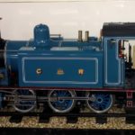
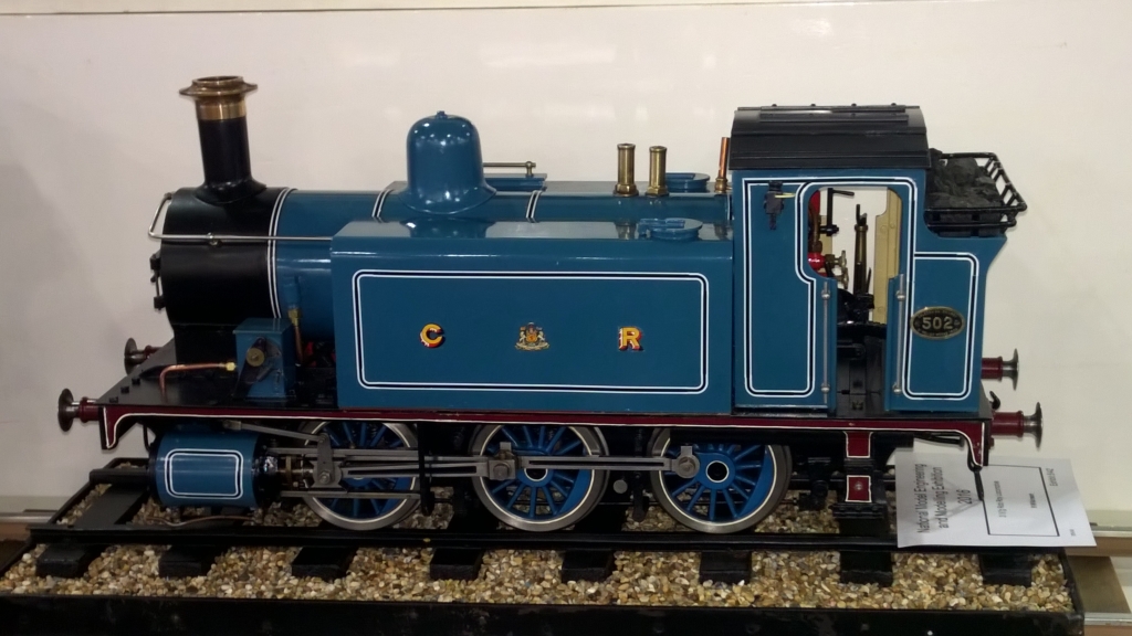
Crampton Loco
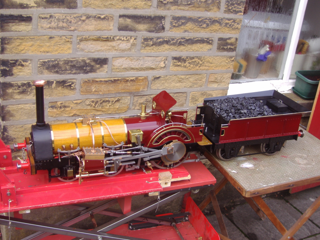
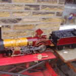
5” Gauge Crampton Locomotive
In the 1840s, when Thomas Crampton, who was a versatile engineer, was developing his designs for the steam locomotive, it was thought that a low centre of gravity (hence a low-slung boiler) and large, rear-mounted driving wheels (for speed and stability) were necessary for success. At first, he designed some unusual-looking engines, but these evolved into what we now regard as the classic Crampton – four or six small carrying wheels beneath the boiler, and two driving wheels mounted behind the firebox. There was relatively little weight on the driving wheels; to improve adhesion, it was found necessary to put cast iron weights beneath the cab footplate.
These engines were not very popular in Britain, where there were only 42 in use, mainly in the Kent area, but there were large numbers in regular use on the continent, especially in France and Germany, and smaller numbers in Denmark, New Zealand, North America and other countries.
 This 5” gauge locomotive, designed by Brian Arridge, does not represent any particular prototype, but is unmistakably a classic Crampton, with a single pair of large driving wheels set behind the boiler, and outside Stephenson’s valve gear with large eccentrics. The tender is of simple design, with coil springs above the axle-boxes. The emergency hand-pump is hidden beneath the tool-chest.
The locomotive has leaf springs on the carrying wheels, and coil springs below the drivers. The slide valves above the inclined port faces are operated by Stephenson gear with large eccentrics on the outer side of the driving wheels. The front and rear flanged plates of the smokebox are identical apart from different apertures.
The copper boiler is a conventional locomotive type. No superheating is provided, as the regulator valve is situated directly on top of the boiler. There are seventeen 7/16 in. (o/d) tubes. Some of the original Cramptons had boilers with an oval cross-section so that they could be placed lower inside the frames.
It was necessary to use three solders of different melting points and an epoxy adhesive in order to build up the splashers and apply the half-round beading to them and the cab side plates.
This engine had a successful steam test in September 2019. It was intended to paint and complete it before the 2020 running season, but the Covid-19 lockdown delayed matters. Reassembly after painting (my thanks to Ken Shipley for this) was not finished until October 2020. It is hoped that steaming will take place sometime in 2021.
Room was found beneath the cab footplate for a 5lb lump of lead. It will be interesting to see the effect of this on the loco’s performance.
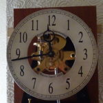
8 Day Wall Clock
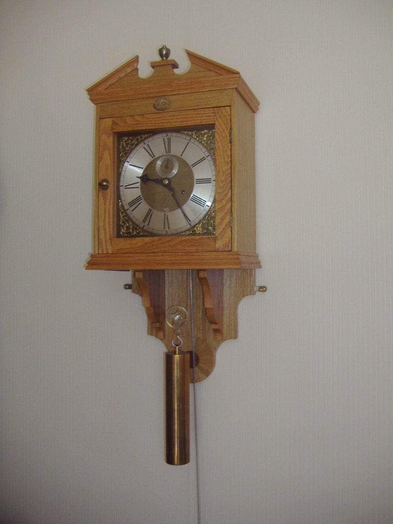
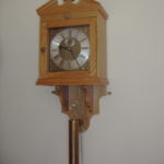
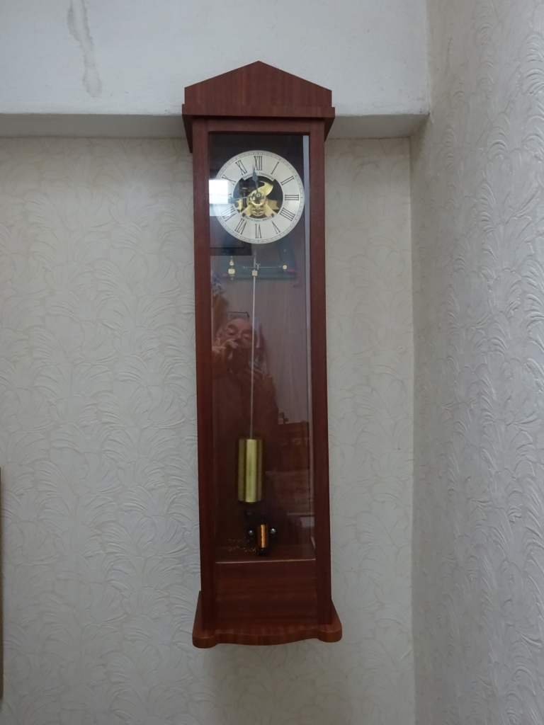
8-Day, Weight-Driven Wall Clock
with Striking Mechanism and Perpetual Calendar
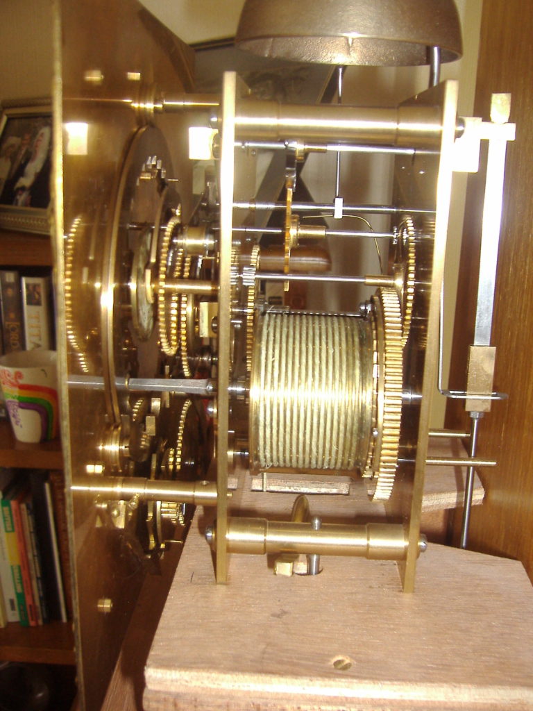
John Wilding designed this clock, which has a basic weight-driven going train. Most of the wheels were cut using a home-made cutter frame and single-pointed fly cutter; the pinions were cut with a home-made multi-tooth cutter. Division was accomplished with a simple dividing head using the Myford change wheels.
The pendulum bob was constructed from two brass shells spun over a wooden former and soft-soldered together before filling with lead. The weight is a length of brass bar.
The striking mechanism derives its power from the pendulum. Thus only one train is required. Henry Ward invented this system in 1805.
The datework was devised around 1740 by William Ludlum; it makes allowances for different lengths of months and leap years.
 The case is constructed from oak-veneered ply-wood, with solid oak sections and flat pieces, e.g. the doorframe, supports for the shelf and various mouldings.
The dial is made in the traditional manner. The chapter ring was engraved on the lathe, the numerals being wax filled before silvering the ring. The Arabic numerals on the date ring were engraved by a professional engraver; the numerals were wax filled before the ring was silvered.
Bought-in items:
Spandrels (corner decorations on the dial)
Cartouche (name and date plate)
Engraved numerals on date ring
Random Photo